
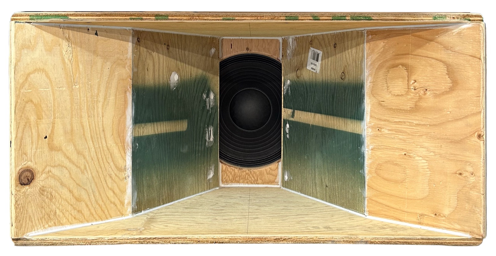
Until the wedge is built, the mid is a Dayton PA310-8 12" in a DIY horn with a 6" x 14" throat, on DCX output 4. It is the band that limits the rig as built: at its 450 W limiter it reaches 128.6 dB, and every other band is trimmed to sit on the house curve against it.
Cone travel is no concern here. At the limiter the worst case in its band is about 0.5 mm, a tenth of Xmax, so heat sets the limit.
The wedge is the mid-range box we are building for the top of the stack: one JBL 2123H 10" driver loaded by a short four-panel horn, made from ¾" birch plywood. It sits under the JBL 2350 radial horn, so the top is one horn and one 10". It replaces the Dayton PA310-8 on DCX output 4.
The outside is the 2350's own box footprint, measured 24" front to back on 2026-10-17. The 2350 sits on top with the boxes flush; its horn mouth stands proud of both. We have drawn it but not built it yet (sheet rev h).
The ends of the top and bottom horn panels show as ¾" lips above and below the mouth. The spaces above and below the horn panels are sealed dead air (voids). Line the back of the rear chamber with 1" fibreglass.
The slot plate sits over the 8¾" rear-mount hole; the dashed circles are the driver's cone and dust cap behind it. The horn walls run from the slot out to the 30⅛" × 18" mouth.
Top and bottom horn panels at 15¾° (shown 16°), with sealed voids behind them. Slot plate, throat plate, driver, rear chamber and back from front to rear.
Side walls at 37⅛° to the axis, 74° across. The box narrows along the horn walls to the 12½" tail that holds the driver.
All parts ¾" ply. Sizes in inches. Blade tilt is the table-saw bevel for the edges named.
| Part | Qty | Size | Blade tilt |
|---|---|---|---|
| Box top / bottom: 32" front narrowing to 7⅜" at 16¼" back, step to 12½", straight back. Cut as a pair. | 2 | 32 x 24 blank | 0° (square) |
| Side walls (= box sides), ends parallel | 2 | 19½ x 20⅜ | ends 37⅛° |
| Horn top / bottom: trapezoid 5½ to 30⅛, 16⅞ on center line; mark on the horn face | 2 | sides 20⅞ long | sides 9½° ends 15¾° |
| Slot plate, 5½ x 8¾ slot | 1 | 12½ x 19½ | 0° |
| Throat plate, 8¾" hole | 1 | 12½ x 19½ | 0° |
| Tail sides | 2 | 5½ x 19½ | 0° |
| Back, screwed on with gasket | 1 | 12½ x 19½ | 0° |
About 22 sq ft: one 4 x 8 sheet. About 55 lb with the driver.
Every exposed plywood edge gets a 3/8" corner-round, routed after glue-up. Leave square any edge that is a joint or a mating face.
37⅛°, side wall ends. Both ends tilt the same way, a parallelogram seen from above: one end sits flat on the slot plate, the other is flush with the front.
15¾°, horn top and bottom panel ends. Parallel too. The mouth end sits flush with the front, its back corner just touching the box top.
9½°, horn top and bottom panel side edges, where they meet the side walls. This is the only compound joint. The horn face is the wider face.
Test each setting on scrap. Hairline gaps are fine if caulked airtight.
| Mid | 2.83 V, 300-700 Hz | Max |
|---|---|---|
| Dayton PA310-8 in its horn (now) | about 102 dB | 128.6 dB |
| 2123H in this 32" wedge | about 108 dB | 132.6 dB |
Model: JBL spec-sheet data, plane-wave horn, half-space, 1 m on-axis, corrected to the datasheet (+0.8 dB). Measure the built box with REW.
The wedge takes the Dayton's place: no extra amp and no Y-cable. The kicks lie flat, side by side; the wedge sits centered on their seam, the 2350 directly on top with the fronts flush, and the piezo plate on the 2350.
After installing: set the delay against the 2350, check polarity at 300 and 700 Hz, then set trims. Expect the mid about 2-3 dB up on the Dayton.
With the house-curve balance held, the wedge lifts the mid above the rest. Since build sheet rev m (2026-10-18) the scoops are limited for cone travel, so they bind first, at a mid level of about 129.7 dB: about +1.1 dB over the Dayton rig (128.6). The 2440 horn binds next (131.3), then the kicks (133.7). The mid then has headroom to spare.
Later, a second 2350 and wedge as a second top would relieve the horn; the scoops still set the ceiling.